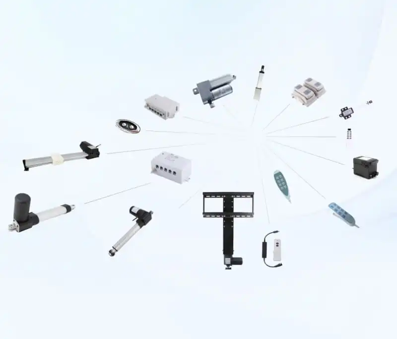
Linear Actuator Driver Full Wiring Instruction, Control Methods And Product Matching Tutorial
If you search for linear actuator related technical content on Google, the search term Linear Actuator Driver always maintains stable search volume, which can be verified from the query data of Google Search Console. Many buyers who purchase mini linear actuators from China’s actuator manufacturers will encounter three core troubles: they cannot find a complete wiring tutorial for this control component, do not know which control mode matches their equipment, and fail to select the correct control unit for FD series linear actuators.
As a professional linear actuator manufacturer with complete production lines of FD10, FD16, FD17, SXTL TV Lift and other mini linear actuators, we have sorted out a full set of practical content around Linear Actuator Driver, covering wiring steps, control mode classification, model matching rules, fault troubleshooting and application scene matching. This guide can help industrial automation buyers, smart furniture manufacturers and medical equipment designers quickly master the use logic of this control unit, and avoid extra procurement losses caused by mismatched control hardware and linear actuators.
The demand for this motion control unit comes from a wide range of downstream industries. Customers engaged in smart sofa lifting, hospital medical bed adjustment, skylight automatic opening and closing, industrial small lifting equipment all need to configure supporting control hardware. Many small and medium purchasers only pay attention to the parameters of linear actuators themselves, but ignore the matching parameters of Linear Actuator Driver, which leads to slow operation of actuators, abnormal noise, insufficient thrust and even circuit burnout after installation. This article systematically solves all common problems related to this control unit, and provides clear matching suggestions combined with our mainstream FD series linear actuator driver.
Chapter 1 Basic Parameter Definition of Linear Actuator Driver
Linear Actuator Driver is the core control component that transmits power and signal to linear actuator motors. The working performance of linear actuator driver is directly limited by the output voltage, output current and signal control mode of this unit. Before wiring and matching, buyers must confirm three core parameters to avoid equipment failure.
First, the rated working voltage of the control hardware. The mainstream specifications on the market are divided into 12V and 24V, which correspond to the power supply specifications of most mini linear actuators. Our FD series linear actuators mainly support 12V and 24V power input, so the matching control unit must select the same voltage specification. If the voltage of the control hardware is higher than the rated voltage of the linear actuator, the motor will heat up rapidly and shorten the service life; if the voltage is too low, the linear actuator driver cannot reach the rated thrust and stroke speed.
Second, the maximum output current of the control unit. Each type of linear actuator has a fixed operating current when reaching full load thrust. The output current of the matching hardware must be higher than the full-load current of the matched linear actuator. Taking FD17 mini linear actuator driver as an example, its full-load working current is 2.1A, so the selected Linear Actuator Driver needs to support a continuous output current of more than 2.5A to ensure stable operation under long-term load.
Third, the signal control interface of the control hardware. The mainstream control types include wired manual control, wireless remote control, synchronous linkage control and PLC signal control. Different downstream equipment has different requirements for the control interface. Smart furniture factories mostly choose wireless remote control type hardware; industrial automation equipment buyers prefer PLC signal compatible units; medical bed manufacturers usually customize synchronous linkage hardware to realize multi-group actuator simultaneous lifting.
Many buyers consult us about the parameter matching standards of this control unit every month. According to our after-sales statistical data, more than 60% of equipment abnormal problems are caused by mismatched parameters of control hardware and linear actuators. Therefore, confirming the three core parameters of Linear Actuator Driver is the primary step before wiring installation. For industry-standard parameter matching standards, you can refer to professional guidelines from global automation media: motor driver selection for linear motion systems.
Chapter 2 Complete Step-by-Step Wiring Tutorial for Linear Actuator Driver
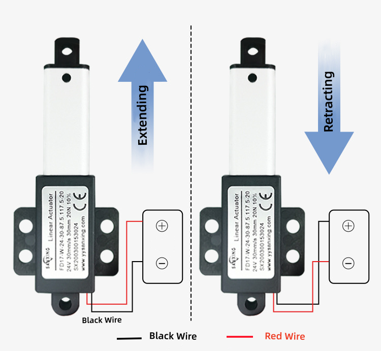
The wiring operation of this control unit is the most frequent technical problem consulted by customers, and unreasonable wiring will directly lead to the failure of the hardware to drive the linear actuator normally. This chapter sorts out the standard wiring steps of universal control units, which is applicable to all FD series linear actuators sold by our factory.
Step 1 Distinguish the wire port definition of the control hardware All standard control products are equipped with four groups of wiring terminals: power input terminal, motor output terminal, control signal terminal and limit switch signal terminal. The power input terminal is used to connect the external power supply of the unit; the motor output terminal is connected to the positive and negative poles of the linear actuator motor; the control signal terminal is connected to remote control, wired switch or PLC equipment; the limit switch terminal is connected to the built-in stroke limit line of the linear actuator to realize automatic stop when the actuator reaches the maximum stroke.
Step 2 Connect the power supply line to the control unit Before connecting the power supply, cut off all external power sources to prevent short circuit and burn the circuit board of the hardware. Align the positive and negative power lines with the positive and negative terminals of the power input port, tighten the terminal screws, and ensure that the wire contact is tight without virtual connection. Virtual connection of power lines will cause unstable power supply of the control unit, resulting in intermittent jitter of linear actuator during operation.
Step 3 Connect linear actuator motor wire to the control hardware Take FD16 waterproof linear actuator as the matching object for wiring demonstration. The two thick wires of the linear actuator motor are positive and negative power lines, which are connected to the two motor output terminals of the unit respectively. If the linear actuator runs in reverse stroke after wiring, exchange the positive and negative wires of the motor terminal to adjust the forward and reverse movement direction. It should be noted that do not connect the limit switch wire to the motor terminal by mistake, otherwise the limit protection function will fail.
Step 4 Access the limit switch signal wire to the control unit Mini linear actuators such as FD10 compact micro linear actuator are equipped with built-in upper and lower stroke limit switches, and the corresponding signal wires need to be connected to the limit terminal of the hardware. After the connection is completed, when the linear actuator extends to the maximum stroke or retracts to the minimum stroke, the limit switch will send a signal to the control unit, and the hardware will automatically cut off the motor power to avoid mechanical collision damage of the actuator. If the limit wire is not connected, the linear actuator will keep running after reaching the stroke limit, resulting in deformation of the internal screw structure.
Step 5 Connect the control signal equipment to the control hardware According to the actual use scenario, connect remote control receiver, wired hand controller or PLC signal line to the control signal terminal. For the synchronous control scheme of multiple linear actuators, connect the signal synchronization line between multiple control units to realize synchronous lifting of multiple groups of actuators, which is widely used in TV lifting cabinets and multi-section medical beds equipped with SXTL tv lift linear actuator driver.
Step 6 Power on test operation of the control unit After all wiring is completed, check all terminals again to eliminate short circuit hidden dangers, then turn on the power supply to test the forward and reverse stroke of the linear actuator. If the linear actuator responds sensitively and the limit stop function works normally, the wiring process is completed. If there is no action after power on, recheck whether the positive and negative poles of the power supply of Linear Actuator Driver are reversed and whether the motor wire terminals are loose. To avoid circuit wiring errors in mass assembly, you can learn standard circuit design logic here: linear actuator drive circuit design basics.
For buyers without professional electrical technicians, we provide customized wiring harness matching control units and FD series linear actuators. The wiring harness is pre-divided with color codes, which can reduce the wiring error rate by more than 80%, and save the installation time of on-site equipment assembly.
Chapter 3 Four Main Control Modes of Linear Actuator Driver and Applicable Scenarios
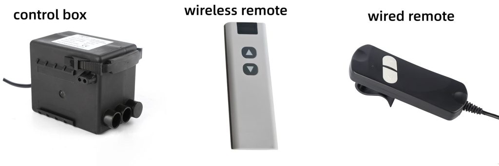
Different structural designs of this control unit correspond to different control modes, and buyers need to select the corresponding hardware according to their downstream product positioning. This chapter introduces the advantages, disadvantages and matching customer groups of four mainstream control types.
- Wired manual control hardware This type of unit is equipped with a wired hand controller, which realizes stroke control through physical buttons. The cost is low, the circuit structure is simple, and the failure rate is extremely low, which is suitable for small batch production of simple lifting equipment. The disadvantage is that the control distance is limited by the length of the wire, which cannot realize remote wireless operation. Small skylight equipment manufacturers and small mechanical test equipment buyers mostly choose this type.
- RF wireless remote control hardware Wireless remote control units are the most widely used type in smart furniture industry. The built-in signal receiving module can receive remote control signals within 10–30 meters without wiring between the controller and hardware. Smart sofa, electric lifting table and TV cabinet manufacturers all prefer to match wireless remote control units for FD10, FD17 and other mini linear actuators. Our factory can customize multi-group remote control frequency bands to avoid signal interference between multiple sets of equipment.
- Synchronous linkage control hardware Synchronous units are specially designed for equipment that requires multiple linear actuators to lift at the same speed and height. The internal signal synchronization module can unify the output power signal of each hardware, so that the stroke error of multiple linear actuators is controlled within 2mm. Medical bed, large smart sofa and multi-section TV lifting system manufacturers need to purchase synchronous linkage hardware. If ordinary independent units are used for multi-actuator linkage, the lifting speed inconsistency will lead to equipment skew and abnormal noise.
- PLC compatible control hardware Industrial automation production lines need to connect linear actuators to PLC control systems, so PLC compatible units are required. This kind of hardware reserves standard signal input terminals, which can receive digital signals sent by PLC to realize automatic stroke cycle control. Factory automation equipment, agricultural intelligent lifting machinery buyers are the main customers of PLC compatible hardware. The circuit structure is more complex, and the production cost is higher than ordinary wireless units.
When selecting control hardware, buyers should not only refer to the control mode, but also combine the long-term production cost and after-sales maintenance difficulty of the product. We will provide customers with free matching suggestions according to their finished product parameters, and avoid buyers purchasing inappropriate hardware leading to product rework.
Chapter 4 Matching Rules of Linear Actuator Driver and FD Series Linear Actuator
Combined with the sales data of our FD series linear actuators and the after-sales maintenance records of control units in the past six months, we summarize the fixed matching rules for each model of linear actuator, which buyers can directly refer to for procurement.
- Matching hardware for FD10 compact micro linear actuator driver FD10 is a miniature low-thrust linear actuator with a full-load current of 1.6A, and the matched unit needs to support 12V/24V dual voltage and continuous output current ≥2A. Wired or wireless remote control hardware can be selected, and synchronous units can be customized if multi-group linkage is required. This combination is widely used in small office lifting equipment and miniature skylight opening devices.
- Matching hardware for FD17 mini linear actuator FD17 is the best-selling mini linear actuator driver in our factory, with a full-load current of 2.1A and a rated voltage of 12V as the mainstream. The standard matching unit is 12V wireless remote control hardware with continuous output current ≥2.5A. For medical bed customers with multi-group linkage requirements, we will configure synchronous linkage hardware for FD17 to ensure stable synchronous operation of multiple actuators.
- Matching hardware for FD16 waterproof linear actuator FD16 supports IP68 waterproof grade, which is mostly used in outdoor automation equipment, so the matched unit needs to select the waterproof sealed circuit board version. The full-load current of FD16 is 2.4A, and the output current of the supporting hardware must exceed 3A to cope with the unstable power supply environment of outdoor equipment. PLC compatible units are the mainstream choice for outdoor industrial equipment buyers.
- Matching hardware for SX631 tv lift linear actuator SX631 is a special linear actuator driver for TV lifting cabinets, which generally requires two groups of actuators to run synchronously. Therefore, the matched unit must be a synchronous linkage type, which can control two SX631 linear actuators to lift and retract at the same speed. The mainstream voltage of SX631 is 24V, so the supporting hardware is uniformly 24V specification.
Many buyers will ask whether a single control unit can drive multiple linear actuators of different models. According to the test data of our laboratory, the same hardware can only match linear actuators with the same voltage and similar full-load current. If high-thrust and low-thrust linear actuators are connected to the same unit, the current distribution will be unbalanced, resulting in the low-thrust actuator running fast and the high-thrust actuator running slow, which will seriously affect the service life of both the control hardware and linear actuators.
Chapter 5 Common Faults of Control Units and Quick Troubleshooting Solutions
In the daily after-sales consultation, the failure problems of motion control hardware account for more than 40% of all technical consulting content. We sort out the four most frequent faults and simple self-inspection solutions, which can help buyers quickly eliminate minor faults without returning goods for repair.
Fault 1 The control unit is powered on but the linear actuator does not move Possible reasons: The positive and negative poles of the power supply are reversed; the motor wire terminal is loose; the limit switch wire is short-circuited. Troubleshooting: Reconnect the power supply positive and negative poles; re-tighten all motor terminals; disconnect the limit wire and test separately. If the actuator runs normally after disconnecting the limit wire, replace the internal limit switch of the linear actuator.
Fault 2 The control unit outputs abnormal noise during operation Possible reasons: The output current does not match the full-load current of the linear actuator driver; the internal circuit has virtual welding; the linear actuator is stuck by foreign objects. Troubleshooting: Replace the matched specification control hardware; send the faulty unit back to the factory for circuit inspection; disassemble the linear actuator to clean the internal sundries.
Fault 3 The control unit automatically cuts off power during full-load operation Possible reasons: The maximum output current is lower than the full-load current of the actuator; the heat dissipation is poor, triggering overheating protection. Troubleshooting: Upgrade to a high-current specification hardware; add heat dissipation gaskets around the installation position to avoid closed heat accumulation environment.
Fault 4 The signal of wireless remote control unit is delayed or lost Possible reasons: The signal receiving antenna is blocked by metal objects; multiple groups of hardware share the same remote control frequency band. Troubleshooting: Adjust the installation position to avoid metal shielding; customize independent frequency bands for different groups of control units.
Most minor faults can be solved through on-site self-inspection, and only the circuit board damage caused by short circuit needs to be returned to the factory for maintenance. Our factory provides one-year free warranty service for all supporting control hardware, and technical engineers can provide remote video guidance for fault troubleshooting at any time.
Chapter 6 Application Industry Matching of Control Hardware
The applicable industries of motion control units cover almost all small automatic lifting equipment industries, and different industries have differentiated customized requirements for the structure and parameters of the hardware.
- Motor driver selection standard for linear motion equipment: https://www.automationworld.com/control-systems/article/13462820/motor-driver-selection-for-linear-motion-systems This article systematically expounds the current matching standard of linear motor driver in the global automation industry, including the current calculation formula of small linear actuator driver, which can be used as the auxiliary reference standard for purchasing supporting control hardware.
- Linear drive circuit design basic tutorial: https://www.machinedesign.com/mechanical-motion-systems/article/21831245/linear-actuator-drive-circuit-design-basics The article introduces the circuit protection design points of miniature linear actuator driver, which can help electrical engineers optimize the wiring scheme of control units and reduce the failure rate of equipment in mass production.
Conclusion
Linear Actuator Driver is an indispensable supporting component of all electric mini linear actuators. Whether buyers are engaged in smart furniture, medical equipment or industrial automation production, they must confirm the voltage, current and control mode matching standards before mass procurement. Unreasonable selection and wiring of this control hardware will bring hidden dangers to the after-sales quality of finished products and increase the maintenance cost of buyers.
As a professional linear actuator manufacturer integrating R&D, production and customization, we can provide complete sets of matching solutions of linear actuator + supporting control hardware, support custom stroke, voltage, control mode of actuators and matching units, and provide free sample testing service for global buyers. If you have any matching, wiring or procurement questions about this control unit, you can send RFQ information to our official mailbox, and our technical sales team will reply with targeted solutions within 24 hours.
RFQ 1
Q: I don’t know how to match the right Linear Actuator Driver for my FD17 mini linear actuator, can you give fixed parameter standards?
A: 12V, ≥2.5A output current, wireless remote or synchronous driver optional.
RFQ 2
Q: After wiring Linear Actuator Driver, the linear actuator does not move, how to troubleshoot quickly?
A: Check power positive/negative, motor terminal looseness and limit wire short circuit in sequence.
RFQ 3
Q: Need multiple linear actuators to lift synchronously, which type of Linear Actuator Driver should I buy?
A: Select synchronous linkage Linear Actuator Driver for multi-group actuator simultaneous operation.
RFQ 4
Q: My equipment is used outdoors, do I need a special waterproof Linear Actuator Driver?
A: Yes, match sealed waterproof circuit board Linear Actuator Driver with FD16 IP68 actuator.
RFQ 5
Q: Can I customize the remote control frequency of wireless Linear Actuator Driver to avoid signal interference?
A: Support exclusive frequency band customization for bulk orders, no cross-signal interference.