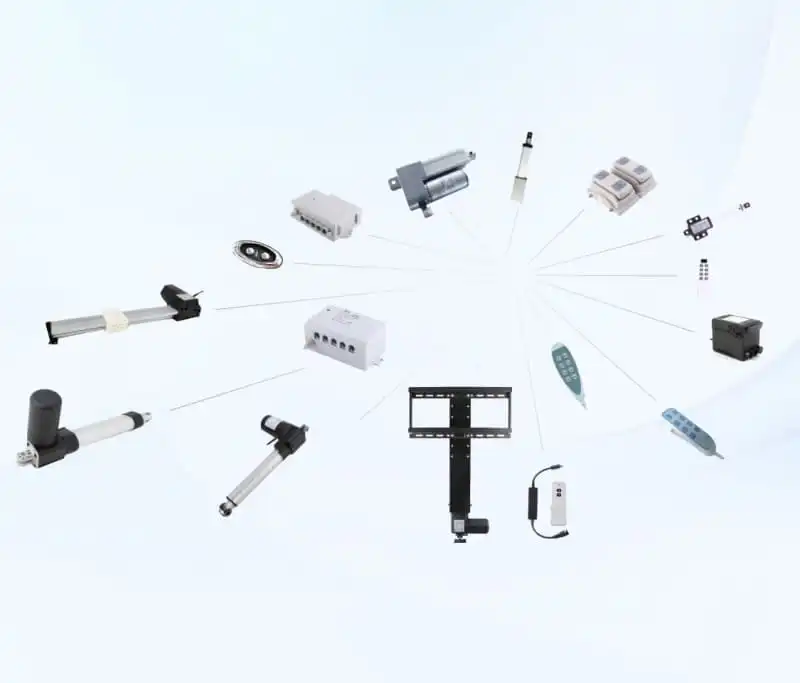
Every electric linear actuator delivers mechanical push‑pull motion, yet many system designers overlook supporting hardware before integration. If you want reliable, repeatable motion performance, understanding how to control a linear actuator becomes the foundation of your whole mechanical design project. Many first‑time integrators only order actuator units and later realize missing accessories prevent normal operation, wasting project time and prototype budgets. Learning how to control a linear actuator correctly helps mechanical engineers, OEM purchasers and technical designers avoid common wiring mistakes, overload damage and unstable motion output.
Before diving into hardware lists, you should clarify your application goals when you learn how to control a linear actuator. Simple on‑off movement for furniture adjustment demands far simpler hardware than precise position feedback for industrial automation equipment. The working voltage of your selected actuator defines nearly every compatible control accessory. Most compact DC electric actuators on the market adopt 12V DC or 24V DC working standards, matching mainstream industrial power modules. FD10 compact linear actuator works perfectly within these two common voltage ranges for light‑to‑medium thrust projects. When you master how to control a linear actuator, you can match accessories according to real‑world thrust, stroke and environmental requirements, instead of selecting parts purely based on product price.
When engineers start evaluating motion solutions, they frequently ask what physical parts are mandatory to run electric push‑rods. Simply connecting a linear actuator directly to a DC power source can make it extend and retract, yet you gain zero control over stopping points, movement speed or direction switching. That is exactly why you need dedicated hardware while figuring out how to control a linear actuator. The core supporting components fall into four major categories: power supply units, actuator controllers, connecting cables & actuator wires, and auxiliary feedback accessories. Each category carries non‑negotiable functions for stable system operation. Before purchasing any parts, spend time learning the core principles of how to control a linear actuator, so you can avoid costly ordering mistakes. Many mechanical engineers spend hours troubleshooting simply because they skip basic guidelines for how to control a linear actuator.
Core Hardware You Need When You Want to Control a Linear Actuator
Linear Actuator Power Supply
The power supply provides matched voltage and continuous current output for your whole motion set. Voltage must strictly match the actuator rated voltage. If you apply 24V power to a 12V actuator, internal motor winding will overheat and burn out rapidly. Insufficient current output leads to slow movement, unstable output thrust and automatic shutdown under load conditions.
You should calculate peak current under maximum working load instead of only checking static no‑load current. For multiple‑actuator synchronized movement, sum peak current value for all units and reserve 30% safety margin for surge current. For outdoor or damp workshop environments, select IP‑rated enclosed power units against dust and moisture interference. FD16 mini linear actuator datasheet lists peak current parameters for your power supply calculation reference.
Many buyers underestimate surge current that occurs the moment the actuator starts moving. DC motors draw much higher current at startup than during steady running. Cheap unregulated wall adapters cannot handle short‑term current spikes, they will trigger over‑current protection and cut output intermittently, even if the nominal current looks enough on paper. Regulated DC power supplies are strongly preferred for long‑term industrial and OEM deployment. Unregulated adapters may work for intermittent short‑cycle household testing, but they are not recommended for equipment that runs daily.
Temperature performance of power supplies is another easily ignored detail. Power supplies generate heat under continuous load. If you install them inside closed compact cabinet without ventilation space, internal temperature will rise, triggering thermal shutdown or shortening service life. Leave enough air circulation space around power modules, avoid stacking other heat‑generating electronic devices directly on top. For high‑temperature workshop environments, select power supplies with wide operating temperature range to guarantee stable output. Without proper power configuration, even the best reference materials cannot teach you how to control a linear actuator successfully. Many beginners skip power evaluation at the very beginning when studying how to control a linear actuator, which leads to later system failure. Even with high‑quality actuators, you cannot get expected results if you ignore power basics for how to control a linear actuator.
Linear Actuator Controller Options
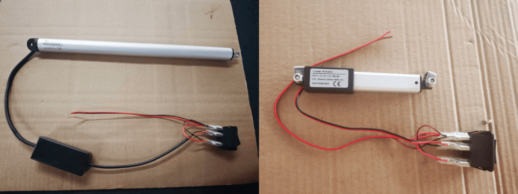
A linear actuator controller serves as the command center. It handles direction reversal, start‑stop signals and optional speed adjustment. Controller types split into manual switch controllers, wired hand‑set controllers, wireless RF remote controllers and PLC‑compatible industrial controllers.
Simple DPDT rocker switches represent the most cost‑effective manual solution for low‑volume non‑automated equipment. Users manually toggle the switch to change motor polarity, realizing extension and retraction movement. This type fits furniture adjustment, small lifting platforms and simple ventilation baffles. Wireless remote controllers remove physical wiring restrictions, ideal for equipment where operators cannot stay close to moving mechanical structures. Industrial‑grade controllers support 0‑10V analog signal, PWM pulse‑width‑modulation signal or bus communication, connecting with PLC or microcontroller systems for automated manufacturing lines. When researching how to control a linear actuator, match controller signal interfaces to your existing host system, otherwise hardware compatibility barriers appear even with correct voltage setup.
It is worth noting that not all controllers support speed adjustment. Many basic low‑cost controllers only offer full‑speed forward and reverse without speed tuning function. If your application requires slow, gentle movement to avoid mechanical impact, you must select models with built‑in PWM speed regulation. Speed adjustment cannot rely simply on lowering input voltage; reducing supply voltage will drop output thrust sharply and may cause motor stalling under load. PWM adjusts duty cycle while keeping rated voltage, preserving full thrust capacity during speed tuning, which is the correct way for speed control of DC linear actuators. Many new designers overlook this principle when learning how to control a linear actuator. Choosing the wrong controller will make it impossible for you to learn how to control a linear actuator as expected. Selecting a suitable controller is one critical step when practicing how to control a linear actuator for industrial projects.
Actuator Wires, Cables and Connector Selection
Actuator wires transmit power and feedback signals between controller and actuator body. Many integration failures trace back to undersized cables or mismatched connectors. Thin gauge wires generate excessive voltage drop under high current, causing thrust loss and slow movement. For long‑distance installation over two meters, upgrade to thicker gauge cables to offset voltage loss.
Different application environments demand different cable properties. Indoor static installation can use standard PVC insulated cables. Mobile reciprocating motion scenarios need flexible high‑cycle‑life drag‑chain cables to prevent core fracture after thousands of movement cycles. Outdoor projects require water‑resistant, oil‑resistant cable jackets. Standard FD‑series actuators adopt customizable connector terminals; you may choose bare wire ends, aviation plugs or automotive‑style connectors according to your assembly workflow. Poor wiring configuration frequently creates hidden faults even if you fully understand how to control a linear actuator.
Connector reliability directly influences whole‑system stability. Loose terminals will produce heat at contact points under load, creating intermittent failure which is hard to reproduce during bench testing. Vibration‑prone machinery such as vehicle‑mounted equipment should use locking‑type connectors instead of simple bare‑wire crimp connections. When you customize cable length, avoid unnecessary overly long cables, extra cable length increases voltage drop risk and occupies cabinet inner space. Proper cable selection is one practical skill you will pick up as you learn how to control a linear actuator. If you ignore cable specification, you cannot reliably master how to control a linear actuator no matter how good your controller is. Correct wiring practice prevents many headaches when you implement how to control a linear actuator on real‑world machines.
Feedback Accessories for Position Control
Basic open‑loop setups only complete full‑stroke extension or retraction. If you need intermediate position stopping, you have to add position feedback hardware, including potentiometer feedback, Hall‑effect encoder feedback. Feedback wires send real‑time rod position data back to compatible controllers. Without matched controllers that can read feedback signals, installing feedback sensors delivers zero practical value. You need to verify full compatibility between actuators with feedback and your selected controller hardware before purchasing all components. When exploring how to control a linear actuator with precise positioning, feedback accessories become indispensable parts of your solution.
Potentiometer feedback provides analog position signal with lower cost, suitable for general‑precision positioning scenarios. Hall‑effect encoder delivers high‑resolution pulse signal for high‑precision repeated positioning. Each feedback solution has its own limits: potentiometers will experience wear after millions of cycles, while encoders demand more complex controller decoding modules. Evaluate your required positioning accuracy and expected service cycles before picking feedback hardware, do not blindly pursue higher precision which brings extra cost without real‑world benefit.
Different Control Methods for Linear Actuators
Simple Manual Switch Control
Manual switch control is the most straightforward approach when you learn how to control a linear actuator. A DPDT switch reverses DC motor polarity manually. Middle position cuts power supply to hold position. This solution requires no programming, no complex configuration work. It suits low‑budget projects without automatic logic requirements, such as medical auxiliary beds, home furniture adjustment and small agricultural machinery modifications.
Limit switches built inside most SANXING FD‑series actuators cut power automatically when stroke reaches mechanical end points, protecting motors and mechanical structures from over‑travel damage. You still need manual operation for each movement action. It cannot realize automatic cycle or fixed‑point positioning.
One common oversight for manual switch setup: mechanical holding force after power‑off. Many users assume actuators can hold heavy load indefinitely once power is disconnected. Without self‑locking screw structure, external load may push the rod back. Trapezoidal screw actuators offer good self‑locking performance; ball‑screw models have lower self‑locking capability and may need external mechanical brake for static load holding. This mechanical property must be considered at early design phase, even before you select control hardware.
Wired Hand‑Controller Control
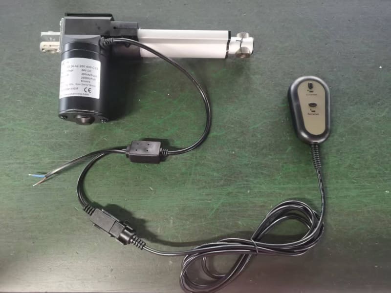
Hand‑controller solutions integrate buttons inside handheld control panels. Operators press extend or retract buttons to operate actuators. Many hand‑controllers support position memory function, storing several preset positions for one‑key recall. This solution is widely adopted in ergonomic lifting tables, rehabilitation medical devices and adjustable workstations. Compared with simple rocker switches, hand‑controllers deliver better user experience, with compact enclosures for convenient installation.
When choosing wired hand controllers, check cable tensile strength. In frequent‑use medical devices, users may pull or tug the hand‑set during operation, poor‑quality thin internal wiring will break after repeated pulling. Industrial grade hand‑sets use strain‑relief design at cable outlet to extend service life.
Wireless Remote Control
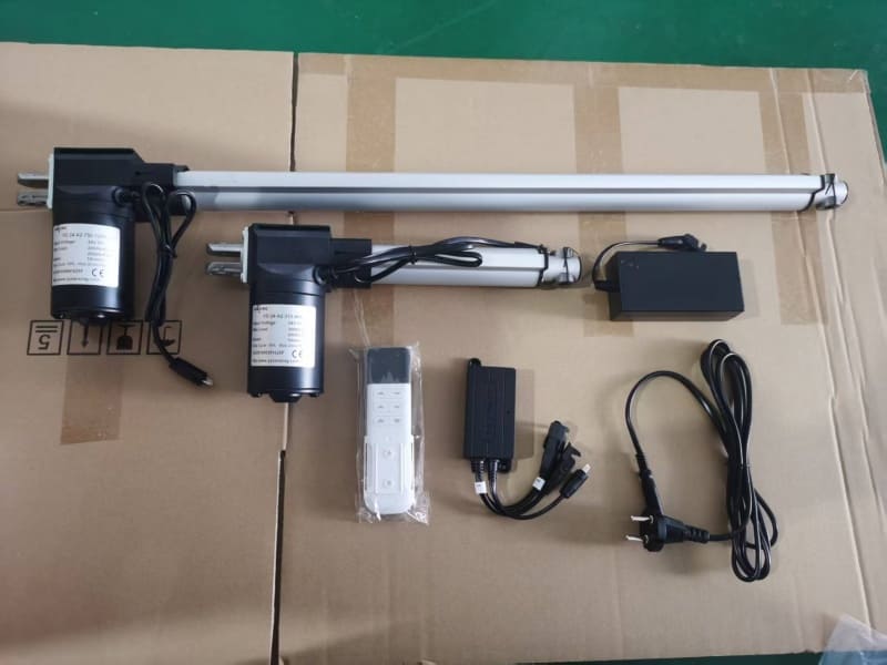
RF wireless controllers remove physical cable links between operators and equipment. Users send wireless commands to trigger actuator movement. This control mode fits equipment where direct physical access proves inconvenient, including large agricultural facilities, special‑purpose vehicles and high‑placement automation devices. You should pay attention to wireless signal shielding: metal housings and dense metal structures weaken RF signal transmission distance.
Wireless control brings extra failure points: signal interference, lost remote pairing, battery depletion of handheld transmitters. For safety‑critical equipment, add hard‑wired emergency stop circuit independent of wireless system. Never rely solely on wireless remote for safety‑related motion functions.
PLC / Microcontroller Automated Control
Industrial automated projects adopt PLC, Arduino or other microcontroller hardware to realize automatic logic control. You can program movement sequences, fixed‑point positioning, multi‑actuator synchronized operation and interlock safety logic. PWM signal control adjusts movement speed precisely by changing duty cycle of pulse signals. Before deploying this scheme, confirm your actuator and controller support corresponding signal protocols. If you have multiple actuators running synchronously, select multi‑channel controllers for coordinated motion. FD25 metal‑housing linear actuator supports custom wiring for third‑party PLC integration for industrial OEM projects.
Many hobby‑level microcontroller IO pins cannot output high current required to drive actuator motors directly. If you connect linear actuator straight to Arduino GPIO ports, you will burn out chip pins instantly. External relay modules or motor driver boards are mandatory intermediate hardware between microcontroller and actuator unit. This mistake appears frequently among prototype developers who are new to learn how to control a linear actuator.
Safety interlock logic is critical for PLC driven systems. You can program limit signal feedback, overload alarm output, emergency stop trigger and fault status notification. When overload occurs, the system can cut power immediately instead of continuously driving against blocked load, preventing mechanical deformation and motor burnout.
Common Mistakes When You Control a Linear Actuator
Even if you know how to control a linear actuator, practical integration brings many avoidable mistakes. The first frequent error is mismatched power supply current. Users only match voltage while ignoring peak current demand, leading to weak output thrust under actual working load. Second, using too‑thin actuator wires for long‑distance wiring creates voltage drop problems. Third, mixing incompatible feedback actuators with ordinary controllers, expecting positioning function without matched signal receiving hardware.
The fourth mistake comes from ignoring environmental factors. Indoor‑only controllers cannot sustain continuous outdoor damp, dusty conditions. For harsh‑site deployment, select controllers with corresponding IP protection grade. Fifth, overlooking safety margin of thrust load. Running actuators constantly under maximum rated thrust shortens service life significantly. You should reserve 1.5 times safety factor for dynamic load conditions. Many system designers skip pre‑assembly bench test and directly install actuators into finished equipment. Bench testing all control components together before mechanical assembly can save massive debugging time.
Another frequently ignored error is inadequate emergency stop setup. Plenty of small‑scale systems only rely on controller software stop function. Software faults or signal loss can disable virtual stop commands. For equipment that may cause injury or hardware damage, install hardware emergency stop circuit which physically cuts motor power independent of controller firmware. Do not fully trust software logic for safety protection.
Over‑cycling is another hidden issue. Every electric linear actuator has rated maximum cycle rate, meaning maximum number of extend‑retract cycles per hour. Continuous rapid cycling will heat the motor beyond allowable temperature range. Even if thrust output looks normal, internal insulation will degrade, shortening overall product lifespan. You need to respect cycle‑rate limits during system programming.
Multi‑Actuator Synchronous Control Considerations
Many mechanical systems need two or more linear actuators working synchronously to lift platforms or drive frames. When you want to control multiple linear actuators together, you cannot simply connect several actuators in parallel to one power source without dedicated multi‑channel controllers. Different actuators have tiny mechanical differences in internal friction and motor performance. Simple parallel connection leads to asynchronous movement, platform tilting and mechanical stress damage.
Dedicated multi‑channel controllers monitor feedback signals of each actuator and fine‑tune output for motion synchronization. When selecting hardware for multi‑actuator setups, confirm controller channel quantity matches actuator count. Calculate total peak current of all actuators and select sufficient‑capacity power supplies. FD17 compact linear actuator is frequently used in dual‑actuator small lifting structures for indoor equipment.
Even with synchronous controllers, you still need mechanical alignment during installation. If mounting points have misalignment, side‑load force will generate during movement. Side load will damage internal gears and lead to synchronization drift over long running time. Good mechanical installation lays the foundation for perfect synchronized motion; electronic compensation cannot fully fix poor mechanical assembly.
How to Match Control Hardware According to Application Scenarios
Furniture and home ergonomic equipment generally choose 12V or 24V low‑voltage DC actuators, paired with simple rocker switches or wired hand‑controllers. No complex positioning function is needed for most furniture projects. Medical rehabilitation equipment demands reliable hand‑controllers, stable power units and noise‑optimized actuators. Low‑noise performance matters for patient‑contact medical apparatus.
Industrial automation equipment usually requires PLC‑compatible controllers, feedback‑enabled actuators and heavy‑duty actuator wires for long‑term continuous‑cycle operation. Outdoor machinery requires high IP grade for actuators, controllers and cables to resist rain, dust and temperature fluctuation. Vehicle‑mounted projects need components that can tolerate voltage fluctuation from vehicle power systems. Every scenario reminds designers: learning how to control a linear actuator is not just selecting one single part, but building a matched complete motion system.
For agricultural outdoor equipment, surge voltage from lightning induction may damage control electronics. Adding surge‑protection modules for power input can extend service life of expensive controllers. Laboratory test benches often require repeatable precise positioning, so encoder feedback and industrial controllers become priority selection instead of low‑cost manual switches. OEM mass‑production projects also need to consider component supply stability, not just unit price. Avoid highly specialized discontinued controller models which bring maintenance trouble after years of equipment operation.
Further Reading on Our Website
If you want to deepen your understanding of electric linear actuators and practical deployment cases, browse more articles and product resources on our website. Our product pages list full technical parameters for FD‑series compact linear actuators, including thrust, stroke, IP rating and wiring requirements. You can compare different actuator models to find hardware matching your project demands. Real‑world application cases also help you avoid common pitfalls while you learn how to control a linear actuator for your own equipment design. For safety‑related design of motion‑driven equipment, you may refer to ISO 10218‑1 safety requirements for industrial robot and drive systems.
Final Summary
Knowing how to control a linear actuator helps you build stable motion systems instead of only purchasing actuator bodies. Always check four core modules: matched power supply, suitable controller, qualified actuator wires and necessary feedback accessories. Match hardware to real‑world application scenarios instead of blindly pursuing low‑cost parts. Bench‑test your whole control system before mechanical installation. SANXING FD‑series compact linear actuators support custom wiring, connectors and feedback options to cooperate with diverse controller hardware for OEM and industrial automation projects.
FAQ Section
Q1: What basic information should I provide when sending RFQ for linear actuator control accessories?
A1: Confirm working voltage, actuator part ( stroke, load capacity and speed ), control mode requirement, working environment and total quantity.
Q2: Can I use my existing PLC directly to control a linear actuator without extra controller?
A2: It depends on PLC output capacity. Most PLC signal ports cannot drive actuator motor directly; you need intermediate drive modules.
Q3: If I need fixed‑position stop, do all linear actuators support position‑memory control?
A3: No. You need actuators with position feedback plus compatible supporting controllers.
Q4: My equipment runs outdoors, which control parts need IP‑protection upgrade?
A4: Actuator, power supply, controller and connecting actuator wires all need matched IP rating.
Q5: How many FD‑series linear actuators can one single multi‑channel controller drive at the same time?
A5: Depends on controller channel count and total peak‑current limit of power supply.