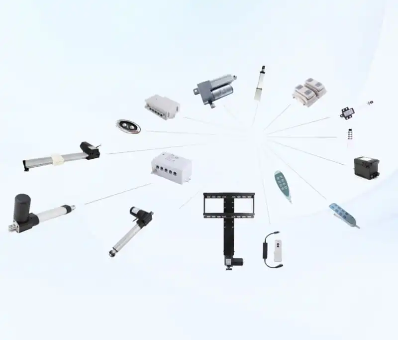
Wondering what is needed to control a linear actuator? Many mechanical engineers and product buyers mistakenly assume a linear actuator will extend and retract automatically once connected to a power source. The truth is, what is needed to control a linear actuator changes based on your project goals, and there is no universal one-size-fits-all hardware set. This guide breaks down popular control options, compares their pros and cons, and helps you figure out exactly what is needed to control a linear actuator for your design. This article focuses only on solution selection. If you want to learn the full list of hardware components for a linear actuator system, visit how-to-control-a-linear-actuator-components. For hands-on wiring tutorials and troubleshooting, follow the dedicated guides linked below. By the end of this article, you will clearly understand what is needed to control a linear actuator for your unique prototype, furniture, or industrial automation project.
Key Factors That Decide What Is Needed to Control a Linear Actuator
Before picking any hardware, you must evaluate core criteria to understand what is needed to control a linear actuator. When you figure out what is needed to control a linear actuator, four core factors define your hardware list: project type, operation mode, special functional requirements, and production stage.
- Project type: Laboratory prototype, adjustable furniture, medical equipment, or heavy industrial automation
- Operation mode: Simple manual operation or automatic cycle controlled by MCU or PLC
- Special requirement: Wireless remote operation, multi-unit coordinated movement, or position feedback
- Production stage: One-off prototype testing or mass OEM manufacturing
Many buyers skip this evaluation step before researching what is needed to control a linear actuator, which often results in mismatched parts, wasted samples, and delayed project timelines. If you want to learn the basic classification of every hardware part in a full actuator system, read how-to-control-a-linear-actuator-components.
Prototype-use considerations when checking what is needed to control a linear actuator
For quick lab testing, what is needed to control a linear actuator can be simplified significantly. A basic DPDT switch, matching DC power supply and fuse are enough to test basic extend and retract movement. This low-cost setup works great for short-duration prototype verification. However, keep in mind this simple prototype configuration is not suitable for commercial mass-produced finished products.
Mass-production OEM considerations when checking what is needed to control a linear actuator
For mass OEM equipment projects, what is needed to control a linear actuator becomes much stricter. You need to evaluate long-term stability, electromagnetic interference resistance, overload protection, circuit safety compliance, and after-sales maintenance. A simple switch solution that works for a prototype often suffers high failure rates once deployed in mass production.
Compare All Available Solutions for What Is Needed to Control a Linear Actuator
Once you define your project conditions, you can assess each available option and determine what is needed to control a linear actuator for your application. The table below compares four mainstream linear actuator control solutions for different use cases.
Linear Actuator Control Solution Comparison Table
| Control Solution | Main hardware | Best-fit scenario | Advantages | Disadvantages | Cost level |
|---|---|---|---|---|---|
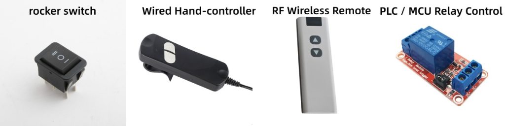
| DPDT Manual Switch | DPDT rocker switch + fuse + DC power supply | Lab prototype, one-off simple test | Low-cost, simple wiring | No wireless function, limited safety protection, not recommended for mass production | Very low |
| Wired Hand-controller | Wired hand-controller + matched controller unit / custom 3-pigtail-cable actuator | Medical bed, adjustable furniture, small lifting device | Plug-and-play, stable and anti-interference | Movement limited by cable length | Low-medium |
| RF Wireless Remote Kit | 12V controller with built-in RF receiving module + remote transmitter | Smart furniture, TV lift, equipment installed in hard-to-reach locations | Wireless operation freedom | Metal enclosures can weaken RF signal; the remote cannot drive the actuator alone | Medium |
| PLC / MCU Relay Control | Relay modules + PLC / microcontroller + DC power supply | Industrial automation, automatic cycles, sensor-triggered motion | Supports complex automatic logic | Requires extra engineering work and electrical programming knowledge | Medium-high |
When you explore what is needed to control a linear actuator, this comparison table helps you quickly rule out unsuitable options. One critical reminder: an RF remote transmitter only sends signals and cannot directly power or drive a linear actuator. A controller equipped with an RF receiver module is mandatory. If you want to view step-by-step DPDT switch wiring instructions, visit 12V wiring diagram tutorial. If you need full controller wiring steps and fault troubleshooting content, go to linear actuator driver matching & wiring guide.
Step-by-Step Workflow To Confirm What Is Needed to Control a Linear Actuator
Follow this simple workflow to confirm exactly what is needed to control a linear actuator for your project:
- Step1: Confirm your linear actuator specifications: rated voltage, full-load current, and cable type (2-wire / custom 3-pigtail-cable)
- Step2: Define your usage scenario: prototype test or mass OEM production? Manual control or automatic operation?
- Step3: Select one control solution from the comparison table above
- Step4: Prepare supporting hardware: matching DC power supply, fuse, and correctly sized wiring
- Step5: Check special functional requirements: multi-actuator coordinated movement? Wireless control? PLC signal input?
- Step6: Double-check hardware compatibility before placing sample orders
Many engineers rush to purchase linear actuators without completing these checks. After receiving the product, they end up confused about what is needed to control a linear actuator.
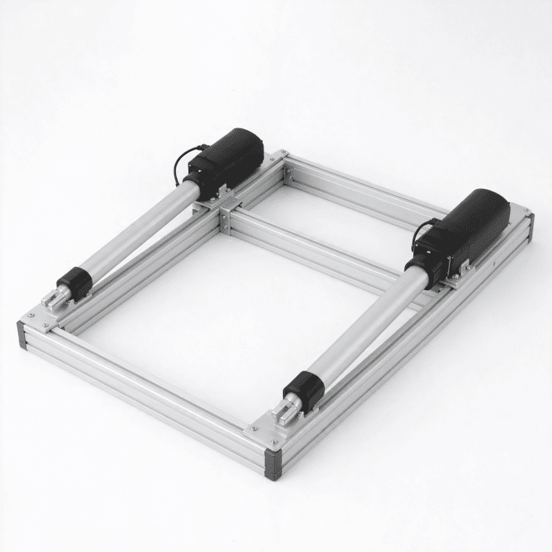
Special case: Multi‑actuator synchronous lifting, what is needed to control a linear actuator
When designing multi-actuator lifting frames, many users wonder what is needed to control a linear actuator to achieve coordinated movement. Important engineering note: Simply wiring multiple linear actuators in parallel to a single power supply will not deliver synchronized motion. Differences in internal friction, mechanical load and manufacturing tolerances between individual actuators will lead to speed deviation, frame tilting and mechanical stress damage.
In theory, dedicated synchronous-type controller hardware is what is needed to control a linear actuator for multi-unit coordinated movement. ⚠️Critical real-world reminder:Even with dedicated synchronous controller hardware, 100% perfect absolute synchronization cannot be guaranteed. Mechanical mounting alignment, side-load, and wear over time will still introduce movement offset. This is a general industry limitation, not specific to one brand of hardware.
For your project evaluation: If your equipment requires strict high-precision synchronized positioning, you need to reserve mechanical tolerance compensation structure on your mechanical frame. Do not rely solely on electronic control to eliminate all deviation.
Common Misconceptions About What Is Needed to Control a Linear Actuator
Many customers hold wrong assumptions when researching what is needed to control a linear actuator. We list the most frequent misunderstandings below:
- ❌ Misconception 1:Just connect power supply, actuator will finish all control work
Fact:Power supply only supplies energy; control hardware defines movement direction and start-stop function. Power alone cannot realize control function.
- ❌ Misconception 2:RF wireless remote can drive linear actuator directly without controller
Fact:Remote is only a signal transmitter; a controller with RF receiving module is mandatory.
- ❌ Misconception 3:Prototype simple hardware can directly apply to mass-production OEM equipment
Fact:Simple switch setup lacks overload and short-circuit protection, creating safety risks for finished commercial products.
- ❌ Misconception 4:All actuators can work with the same set of control hardware
Fact:Hardware must match rated voltage and full-load current; mismatched parameters will burn out the actuator motor.
If you want to go deeper into hardware component classification, refer to how-to-control-a-linear-actuator-components.
To learn more fundamental theory about linear actuator motion characteristics, you can refer to this technical article from Machine Design, a trusted mechanical engineering publication. Machine Design linear actuator basics
FAQ
Q1:What is needed to control a linear actuator for simple lab prototype testing?
A:For simple prototype testing, what is needed to control a linear actuator includes matched‑voltage DC power supply, fuse and DPDT switch. This setup only works for short‑time lab verification, not recommended for commercial finished‑product. For step‑by‑step wiring operation view our 12V wiring diagram article.
Q2:What is needed to control a linear actuator if I want wireless remote function?
A:What is needed to control a linear actuator with RF wireless function includes a 12V controller unit with built‑in RF receiving module plus RF remote transmitter. The remote cannot drive the actuator on its own.
Q3:What is needed to control a linear actuator for multi‑actuator synchronous lifting application?
A:For multi‑actuator synchronous lifting projects, what is needed to control a linear actuator in theory includes dedicated synchronous controller hardware besides adequate power supply. Even with such hardware, 100% absolute synchronization cannot be achieved. Mechanical misalignment, side load and component wear will still create movement offset. If you require high‑precision coordinated motion, mechanical tolerance compensation on your equipment frame is strongly recommended, do not fully depend on electronic control.
Q4:What is needed to control a linear actuator under PLC automatic system?
A:What is needed to control a linear actuator in PLC projects contains relay modules or PLC‑compatible actuator controller. PLC IO port cannot directly output high‑current to drive linear actuator motor.
Q5:Can I skip fuse when figuring out what is needed to control a linear actuator?
A:No. A matched‑rating fuse is essential safety part no matter which solution you choose, even for prototype projects. Skipping fuse brings short‑circuit risk.
Conclusion
There is no universal fixed answer to what is needed to control a linear actuator. Your project stage, manual or automatic requirement, and production quantity all change your required hardware list. Use our comparison table and workflow to filter suitable control solution: DPDT switch for prototype testing; wired hand-controller or RF kit for adjustable furniture; PLC-relay solution for industrial automation; dedicated synchronous controller hardware for multi-actuator lifting frame projects.
Remember the boundary:this article focuses entirely on solution selection. If you need to learn hardware composition view how-to-control-a-linear-actuator-components; for wiring steps open linear actuator driver matching & wiring guide and 12V wiring diagram tutorial.
If you have project requirement for FD‑series linear actuators and supporting control hardware, please submit technical requirement via our contact page. Our sales‑engineering team will give targeted hardware suggestions within 24 working hours.