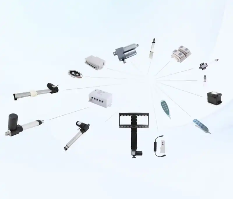
1. Introduction: Why Actuator Sizing Makes or Breaks Industrial Equipment
In industrial machinery, agricultural equipment, and automated factory mechanisms, electric linear actuators provide the essential muscle for mechanical movement. They position heavy hopper doors, tilt lifting tables, and adjust agricultural harvesting mechanisms. However, when operating loads are underestimated or environmental constraints are overlooked, standard actuators frequently fail in the field. Making the right heavy-duty electric linear actuator selection is what ensures dependable, long-term machine operation without unexpected downtime or costly warranty replacements.
A heavy duty electric linear actuator is engineered specifically to deliver high dynamic pushing and pulling power, maintain heavy static holding forces without unpowered drift, and provide reliable mechanical motion under defined operating conditions. Whether you are specifying an 8000N linear actuator like the Sanxing FD1 for high-force industrial tipping beds or choosing a high force industrial actuator like the FD13 with IP66 weather protection for outdoor equipment, matching the actuator to your actual operating environment is the key to project success.
This practical buyer and engineering guide covers every essential aspect of heavy-duty electric linear actuator selection. You will learn why compact actuators fail when overloaded, how to respect critical duty cycle and thermal limits, how waterproofing and load trade-offs affect model selection, and how to choose between the FD1, FD13, and FD22 models for your specific machinery.
2. Why Light-Duty and Compact Actuators Fail in Real Industrial Work
A frequent mistake in machine design is choosing a small, light-duty electric actuator simply because its catalog rating seems close to the nominal weight of the mechanism. In actual service, machinery faces sudden shock loads, off-center twisting forces, internal heat buildup from repeated cycling, and moisture exposure. A successful heavy-duty electric linear actuator selection begins by recognizing the real failure modes that occur when actuators are pushed beyond their design limits.
| +———————————————————————————–+ | 5 REASONS STANDARD ACTUATORS FAIL IN HEAVY-DUTY USE | +———————————————————————————–+ | 1. Gear Stripping –> Undersized gearboxes snap under unexpected shocks | | 2. Back-Drive Creep –> Drive screw slips down when power is turned off | | 3. Bent Extension Rods –> Side loads and long strokes cause binding and wear | | 4. Motor Overheating –> Exceeding the 10% duty cycle burns out motor coils | | 5. Environmental Ingress –> Moisture and dust enter unsealed housings | +———————————————————————————–+ |
2.1. Undersized Gearboxes Cannot Handle Unexpected Shock Loads
Lightweight actuators often rely on thin, low-strength gear sets designed only for smooth, low-load adjustments (such as office furniture). In quiet laboratory testing, they perform adequately. However, when an industrial dump door drops suddenly or agricultural machinery travels over rough terrain, mechanical loads spike instantly.
Under sudden mechanical shocks:
- Undersized gear teeth can shear off, leaving the motor spinning freely without moving the mechanism.
- Excessive gear tooth wear creates mechanical backlash, leading to noisy operation and loose positioning.
- In contrast, a genuine heavy duty electric linear actuator incorporates reinforced, wide-face engineering nylon (POM) gear sets with optimized tooth profiles. These high-grade industrial polymer gear trains absorb vibration, operate with low friction, and deliver immense thrust when paired with a heavy-duty drive screw. During heavy-duty electric linear actuator selection, always ensure the gearbox is rated for your peak dynamic push force.
2.2. Unpowered Slipping and Inadequate Static Holding Force
When electrical power is switched off, you expect your actuator to hold its position firmly. Standard commercial actuators frequently use steep drive screws that turn freely under external mechanical pressure.
In real-world applications:
- If a dump flap, access hatch, or ventilation door relies on an actuator with poor holding power, machine vibration causes the screw to back-drive, allowing the mechanism to sag open.
- In outdoor equipment, continuous wind pressure can push moving linkages out of alignment if the actuator lacks static self-locking strength.
- Heavy-duty actuators are engineered with high-friction self-locking acme drive screws that hold heavy static loads securely without consuming any electrical power. When making your heavy-duty electric linear actuator selection, always verify that the static holding capacity provides substantial headroom over active lifting force.
2.3. Side Loads and Off-Center Twisting Cause Binding and Jamming
Electric linear actuators are designed strictly to push and pull along their longitudinal centerline. However, in real machinery with pivoting hinges, hinge pins wear down and structural frames flex, creating side loads and bending forces on the actuator rod.
Under side load conditions:
- Thin extension tubes bend and deflect under side pressure.
- The inner extension tube rubs against the outer housing, wearing out guide bushings and causing the actuator to bind or jam mid-stroke.
- A well-designed high force industrial actuator utilizes high-strength aluminum alloy inner and outer tubes paired with durable guide bushings to maintain smooth linear travel. When planning your heavy-duty electric linear actuator selection, always install pivoting clevis brackets on both ends to allow the actuator to self-align and eliminate destructive side loads.
2.4. Motor Overheating from Exceeding the 10% Duty Cycle Limit
Standard DC electric actuators are built for intermittent positioning rather than continuous operation. The standard rated duty cycle for industrial electric actuators is 10% (typically meaning a maximum of 2 minutes of continuous operation followed by 18 minutes of rest to cool down).
When actuators are operated too frequently:
- Running an actuator beyond its 10% duty cycle causes internal heat to build up rapidly in the motor windings.
- Excess heat degrades motor insulation, weakens internal brush contacts, and drastically reduces the operating lifespan of the motor.
- Respecting the 10% duty cycle limit is critical. During heavy-duty electric linear actuator selection, always verify that your control system provides sufficient resting time between movements to keep the motor operating within safe thermal limits.
2.5. Environmental Exposure and Matching the Right Ingress Protection (IP)
Different working environments have vastly different sealing requirements:
- Indoor and Protected Applications: For indoor factory equipment, material handling lifters, and dry enclosures, non-waterproof actuators with standard dust protection (such as the FD1) provide maximum force at an economical cost.
- Outdoor and Splash-Exposed Applications: Outdoor machinery exposed to rain, mud, or water splashes requires sealed actuators with IP66 protection (such as the FD13).
- Conservative Protection Planning: It is important to remember that IP66 provides protection against heavy water spray and dust, but it is not designed for continuous underwater submersion or severe chemical immersion. Matching environmental realities to actuator ingress ratings is an essential step in heavy-duty electric linear actuator selection.
3. Practical Sizing Guidelines: Sizing an 8000N Heavy-Duty Actuator
Sizing an actuator requires following sound, practical engineering principles to match thrust, travel speed, duty cycle, and electrical power to your machine. To ensure long-term reliability when selecting an 8000N linear actuator, focus on load capacity margins, thermal rest intervals, stroke length planning, and power supply sizing.
| +———————————————————————————–+ | PRACTICAL 4-STEP ACTUATOR SIZING CHECKLIST | +———————————————————————————–+ | [Step 1] Determine Real Operating Load & Allow Generous Capacity Headroom | | │ | | [Step 2] Respect the 10% Duty Cycle (2 Minutes Run / 18 Minutes Rest) | | │ | | [Step 3] Choose Stroke Length Carefully to Prevent Rod Deflection | | │ | | [Step 4] Match Voltage (12V or 24V DC) and Verify Power Supply Capacity | +———————————————————————————–+ |
3.1. Sizing Load Capacity with Proper Safety Margins
Never size an actuator at its absolute maximum catalog limit for everyday operation. Mechanical friction naturally increases over time as pivot joints collect dust, grease thickens in cold weather, and moving linkages encounter physical resistance.
#### Practical Engineering Sizing Rules:
- Clean Indoor Automation: Specify a moderate reserve capacity above the nominal working weight to account for linkage friction.
- Heavy Industrial Tipping & Flap Mechanisms: Specify generous reserve capacity so the actuator moves heavy materials smoothly without stalling under unexpected overload.
- Conservative Sizing Strategy: Selecting an 8000N linear actuator like the Sanxing FD1 provides massive pushing power for heavy-duty industrial tasks where high thrust is the primary design requirement.
Making a thorough heavy-duty electric linear actuator selection with built-in capacity margin is the most effective way to eliminate field service issues and ensure smooth, reliable movement.
3.2. Duty Cycle Guidelines: Managing Run Time and Heat Dissipation
Duty cycle represents the ratio of active operating time to resting time required for the motor to cool down. Industrial DC electric linear actuators operate with a standard rated duty cycle of 10% under full load.
#### Best Practices for Duty Cycle Management:
- Understand the 10% Rule: A 10% duty cycle corresponds to a maximum of 2 minutes of continuous operation within any 20-minute window (2 minutes on, 18 minutes off).
- Prevent Motor Burnout: If an actuator is operated repeatedly without adequate rest, heat accumulates in the motor windings. Overheating degrades the internal brushes, softens insulation, and significantly shortens the operational life of the actuator.
- Intermittent Positioning Design: Electric linear actuators are ideal for intermittent positioning tasks—such as opening a door, adjusting a chute angle, or tilting a frame every few minutes or hours. If your machine requires continuous back-and-forth cycling every few seconds, consult with engineering specialists for alternative continuous-duty motion technologies.
3.3. Stroke Length Considerations: Managing Push vs. Pull Loads
The mechanical behavior of an actuator depends on whether it is pushing or pulling:
- Pulling Loads (Tension): The aluminum alloy inner extension rod remains straight and stable throughout the entire stroke.
- Pushing Loads (Compression): As stroke length increases, long extension rods become more susceptible to bending under heavy pushing forces.
- Stroke Recommendations: Short to medium stroke lengths (up to 400 mm) handle full rated pushing force with ease. For long strokes (over 500 mm) under heavy pushing loads, ensure that mounting brackets are rigidly aligned and consider external mechanical guide tracks where appropriate.
During your heavy-duty electric linear actuator selection, always verify whether your peak operating load occurs during extension or retraction.
3.4. Speed, Voltage, and Power Supply Guidelines
In DC electric actuators, travel speed and mechanical thrust are directly balanced:
- High-Thrust Operation: An 8000N linear actuator is geared for maximum torque, moving at steady, controlled travel speeds between 4 mm/s and 6 mm/s.
- Moderate-Thrust Operation: Lower-capacity actuators travel faster, moving between 8 mm/s and 12 mm/s.
#### Electrical and Wiring Best Practices:
- Voltage Options (12V vs. 24V DC): Industrial actuators are available in standard 12V DC and 24V DC configurations. 12V DC is common in mobile battery-powered equipment, while 24V DC is widely used in industrial automation cabinets. Choosing 24V DC reduces electrical current draw by half, keeping control wiring cooler and minimizing voltage drop over extended cable runs.
- Startup Inrush Current: When a DC motor starts under load, it briefly draws a surge of current above its normal running level. Ensure that power supplies, circuit breakers, and control relays are sized with adequate current headroom to prevent nuisance tripping.
4. Heavy-Duty Electric Linear Actuator Selection: Product Comparison Matrix
To help equipment builders choose the right hardware, the comparison matrix below highlights three industrial actuator models manufactured by Sanxing Actuator.
4.1. Comparative Specifications: FD1 vs. FD13 vs. FD22
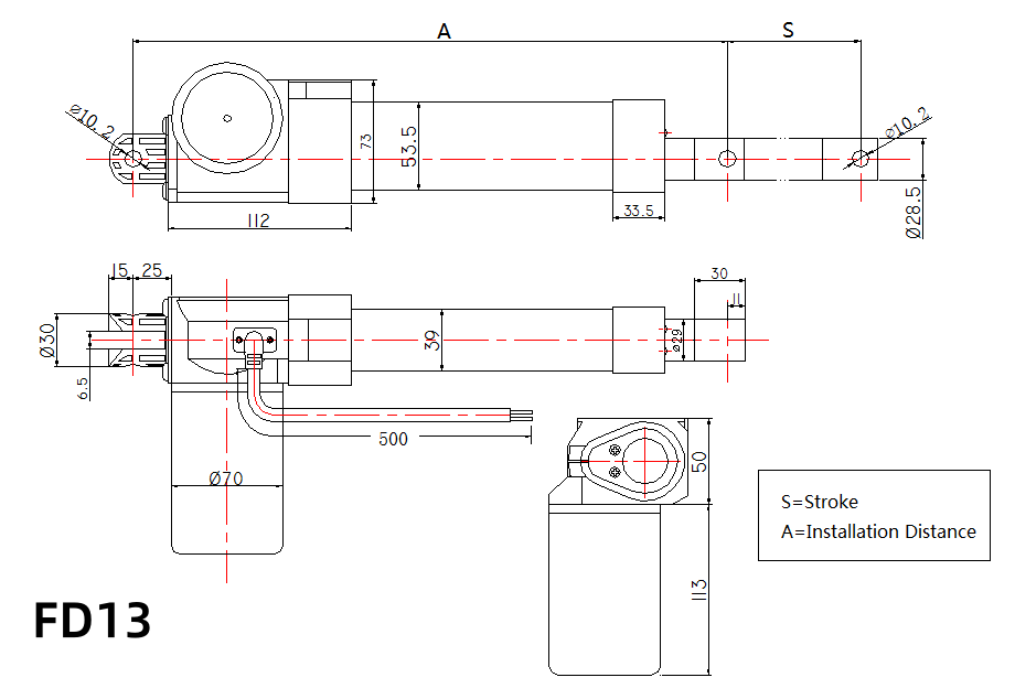
The table below provides accurate technical specifications for the high-force FD1 8000N Heavy-Duty Actuator, the weather-resistant FD13 IP66 Industrial Actuator, and the compact FD22 Heavy-Duty Industrial Actuator.
| Specification Parameter | FD1 Heavy-Duty Series | FD13 Rugged Series | FD22 Compact Series |
| Max Dynamic Push Load | 8,000 N (approx. 1,762 lbs) | 6,000 N (approx. 1,321 lbs) | 6,000 N (approx. 1,321 lbs) |
| Max Static Holding Force | 6,000 N (approx. 1,321 lbs) | 4,000 N (approx. 881 lbs) | 4,000 N (approx. 881 lbs) |
| Standard Stroke Lengths | 26 mm up to 1000 mm | 30 mm up to 1000 mm | 30 mm up to 500 mm |
| Operating Voltage Options | 12V / 24V DC | 12V / 24V DC | 12V / 24V DC |
| No-Load Travel Speed | 4 mm/s – 35 mm/s | 5 mm/s – 35 mm/s | 4 mm/s – 16 mm/s |
| Noise Level | ≤ 48dB | ≤ 48dB | ≤ 48dB |
| Inner & Outer Tube Material | Aluminum Alloy | Aluminum Alloy | Aluminum Alloy |
| Weather Protection Rating | IP44 (Non-Waterproof / Dry Use) | IP66 Water & Dust Resistant | IP44 (Non-Waterproof / Dry Use) |
| Rated Duty Cycle | 10% (Max 2 min on / 18 min off) | 10% (Max 2 min on / 18 min off) | 10% (Max 2 min on / 18 min off) |
| Position Feedback Options | Hall Sensors | No | No |
| Primary Recommended Use | Medical,Furniture, Industry | Agricultural Chutes, Outdoor Adjustments | Medical,Furniture, Industry |
4.2. Practical Model Selection Guide: Matching Model to Application
Understanding the specific strengths and environmental limits of each model ensures a reliable machine design:
- When to Choose the FD1 Series (Maximum Force, Dry / Protected Environments): The FD1 8000N Linear Actuator is Sanxing’s dedicated 8000N high-thrust solution. Built with durable aluminum alloy inner and outer tubes and high-strength engineering nylon gears, it delivers immense pushing power. Important Note: Because the FD1 is non-waterproof, it is recommended for indoor factory machinery, enclosed tipping platforms, industrial dump flaps, and protected mechanisms where massive force is needed and water exposure is not a factor. It is generally not recommended for outdoor solar trackers unless installed in a dry, sheltered location.
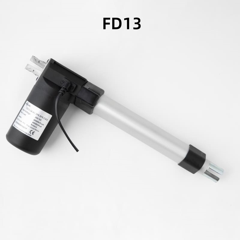
- When to Choose the FD13 Series (Up to 6000N Thrust, IP66 Weather Protection): The FD13 IP66 Waterproof Actuator delivers up to 6000N of dynamic thrust with built-in IP66 weather resistance. It is ideal for outdoor agricultural equipment adjustments, rooftop solar tracking installations requiring rain protection, and outdoor ventilation systems. Conservative Recommendation: While IP66 protects against direct rain and dust, it is not designed for severe chemical corrosion or submerged environments.
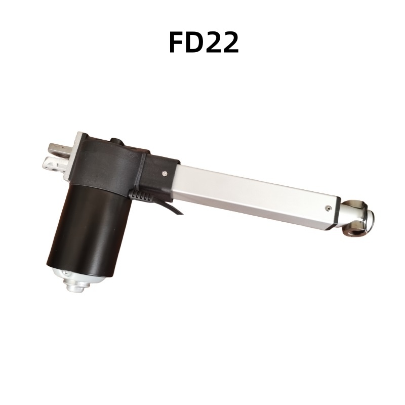
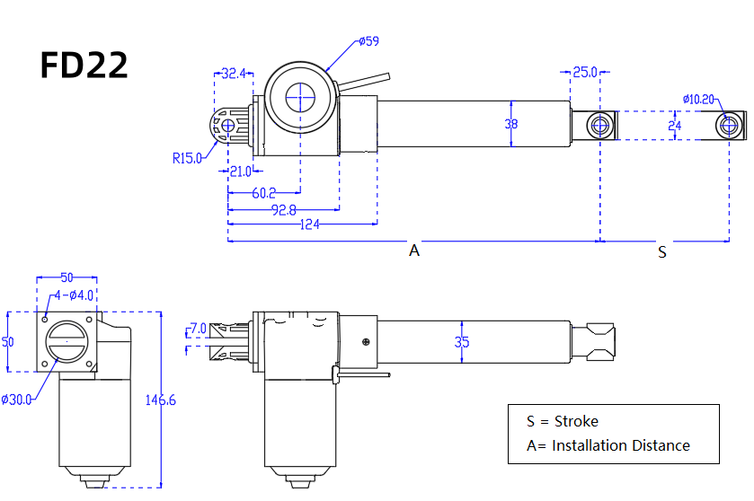
- When to Choose the FD22 Series (Up to 4000N Thrust, Fast & Compact): For indoor factory automation, adjustable assembly tables, or mobile AGVs where installation space is limited and moderate loads must move quickly, the FD22 Industrial Actuator provides an ideal balance of speed and compact power.
5. Heavy-Duty Actuator Applications: Real-World Use Cases
To understand how proper sizing works in practice, let us examine three common industrial applications and how proper heavy-duty electric linear actuator selection solves everyday equipment challenges.
| +———————————————————————————–+ | 3 PROVEN INDUSTRIAL APPLICATIONS & MODEL MATCHING | +———————————————————————————–+ | 1. Solar Trackers & Rooftop Arrays –> FD13 (IP66 Sealing for Rain Protection) | | 2. Agricultural Machinery Chutes –> FD13 (Water/Dust Protection, 10% Cycle) | | 3. Industrial Tipper Beds & Gates –> FD1 (8000N High Force, Indoor/Dry Use) | +———————————————————————————–+ |
5.1. Solar Trackers and Rooftop Adjustable Panels
Solar tracking systems rotate solar panels throughout the day to track the sun and maximize electricity output.
- Outdoor Sealing Requirements: Outdoor solar trackers on rooftops or ground fields are exposed directly to rain and weather. For these applications, an IP66-sealed model like the FD13 is recommended over non-waterproof models.
- High Static Holding: When wind blows across solar panels, it exerts strong twisting forces on the actuator drive. Using an actuator with strong static holding capability locks the panels firmly in position without drawing electrical power.
- Intermittent Positioning: Because solar trackers only make brief position adjustments every few minutes, they naturally comply with the standard 10% duty cycle, ensuring the motor stays cool. According to industrial mechanical motion guidelines published by The Engineering ToolBox, properly matched electromechanical drives and static self-locking mechanisms are essential for long-term structural positioning stability under outdoor wind loads.
5.2. Agricultural Machinery and Off-Highway Equipment
Modern combine harvesters, seeders, and crop sprayers rely on electric actuators to adjust grain unloading spouts, set cutting header heights, and position fertilizer spreading chutes from the tractor cab.
- Vibration Resistance: Agricultural diesel engines and rough field terrain create constant machine vibration. Industrial actuators use securely potted electronics and durable wire connectors that stay connected under shaking.
- Moderate Splash Protection (FD13): The IP66-rated FD13 protects against outdoor rain, mud splashes, and routine washing. However, for longevity, operators should avoid exposing standard actuators to aggressive chemical baths.
- Clean 12V/24V Electric Operation: Replacing leaky hydraulic cylinders with a clean high force industrial actuator eliminates hydraulic fluid spills near crops, reduces system weight, and connects directly to standard 12V or 24V tractor electrical controls.
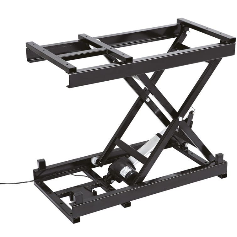
5.3. Scissor Lift Tables
Industrial tipping platforms, bulk aggregate hoppers, and factory sorting gates move heavy bulk materials such as grain, gravel, and metal scrap in dry indoor processing plants.
- Massive 8000N Pushing Force (FD1): scissor lift tables, ergonomic assembly workstations, and mobile material handling carts rely on electric actuators to elevate heavy workpieces, tools, and inventory to comfortable operator heights.
- Overcoming Shallow Initial Angles with 8000N Thrust (FD1): In a collapsed scissor mechanism, the actuator sits at a very shallow mechanical angle relative to the crossing scissor arms. This folded geometry demands immense initial dynamic thrust just to start lifting the load off its base. The FD1 Actuator delivers the massive pushing power required to lift heavy loads smoothly from the fully lowered position.
- Pivoting Clevis Mounting for Angular Freedom: As the scissor arms expand upward, the connection points between the actuator and scissor frame follow a pivoting arc. Pivoting clevis pins fitted at both the rear motor bracket and the front rod end accommodate this angular movement at the mounting points. The FD1 linear actuator itself only extends and retracts in a straight line; this clevis setup isolates the rotary movement to the mounts, transferring strictly axial push forces and eliminating destructive bending stress on the aluminum alloy tube.
6. Sizing Checklist: 8 Practical Questions to Ask Before You Buy
Before ordering or finalizing your equipment specifications, review your application against this practical checklist to ensure a smooth heavy-duty electric linear actuator selection:
| +————————————————————————————————-+ | HEAVY-DUTY ELECTRIC LINEAR ACTUATOR BUYER’S CHECKLIST | +————————————————————————————————-+ | [ ] 1. Real Working Load: Did you allow generous capacity headroom above nominal weight? | | [ ] 2. Static Holding: Can the actuator hold your maximum load when power is switched off? | | [ ] 3. 10% Duty Cycle: Does your control system provide adequate cooling time between runs? | | [ ] 4. Stroke Length: Is your push stroke supported to prevent rod bending under peak load? | | [ ] 5. Pivoting Mounts: Are you using clevis brackets on both ends to eliminate side loads? | | [ ] 6. Water Protection: Is FD13 (IP66) selected for outdoor rain, or FD1 for dry heavy force? | | [ ] 7. Voltage Matching: Is your electrical system configured for 12V DC or 24V DC? | | [ ] 8. Position Feedback: Do you need Hall sensors for position monitoring or synchronized pairs?| +————————————————————————————————-+ |
6.1. Key Mechanical Verification Points
- Match Load to Model Limits: Use the 8000N FD1 for heavy-load dry applications, the 6000N FD13 for weather-exposed applications, and the 4000N FD22 for compact workstations.
- Verify Static Holding Capacity: Confirm that gravity, wind, or vibration will not cause unpowered creep when the machine is stopped.
- Use Pivoting Clevis Mounts: Never weld or rigidly bolt both ends of an actuator if the load moves through an arc. Pivoting mounting pins allow natural alignment and prevent rod bending.
6.2. Electrical and Environmental Verification Points
- Respect the 10% Duty Cycle Limit: Always program sufficient cooling time between movements to avoid overheating the motor windings.
- Voltage Selection (12V vs. 24V DC): Ensure power supplies and controllers match the actuator’s 12V or 24V DC voltage rating.
- Choose the Right Environmental Protection: Use the IP66-rated FD13 for outdoor rain and agricultural splash exposure, and reserve the FD1 for indoor, sheltered, or dry heavy-load applications. Following these practical guidelines during heavy-duty electric linear actuator selection ensures years of trouble-free machine operation.
7. Frequently Asked Questions (FAQ)
Q1: Why is the 10% duty cycle so critical for industrial actuators?
A: Duty cycle prevents motor burnout. Industrial electric actuators are rated for a 10% duty cycle, meaning a maximum of 2 minutes of continuous running followed by 18 minutes of rest to cool down. Exceeding this running limit causes internal heat buildup that damages motor insulation and shortens motor lifespan. Proper heavy-duty electric linear actuator selection ensures your operational cycle matches the actuator’s thermal limits.
Q2: Is the 8000N FD1 actuator waterproof, and can it be used on outdoor solar trackers?
A: No, the FD1 is a non-waterproof actuator designed primarily for dry, indoor, or sheltered industrial environments where massive 8000N force is required. Because outdoor solar trackers are exposed to rain and weather, the FD1 is generally not recommended for outdoor solar trackers unless the customer has no waterproofing requirements or the actuator is housed inside a waterproof enclosure. For outdoor solar tracking requiring rain protection, the IP66-rated FD13 (up to 6000N) is the recommended model.
Q3: How do I prevent side loads from damaging my actuator?
A: Linear actuators are built strictly for straight-line push and pull forces. To prevent destructive side loads, always mount both the rear motor base and the front rod end using pivoting clevis pins. Make sure your load is supported by proper external hinges or linear slide rails so the actuator only pushes straight forward and backward.
Q4: What is the difference between dynamic load and static load?
A: Dynamic load is the actual pushing or pulling force the actuator delivers while moving (for example, the 8000N linear actuator FD1 lifting a heavy machine gate). Static load is the holding force the actuator withstands when its motor is completely powered off without slipping backward or damaging internal components. In machinery exposed to gravity shifts, high static holding capacity is essential.
Q5: Can I run two heavy-duty electric linear actuators together at the same time?
A: Yes, but you cannot simply connect two DC motors to the same switch and expect them to stay perfectly aligned, because minor load and motor rotation speed differences will cause one to travel slightly faster. To keep dual actuators perfectly synchronized, choose models equipped with Hall effect sensors connected to a synchronized dual-channel controller that automatically adjusts speed to keep both rods aligned.
8. Summary & Next Steps for Your Project
Selecting the right linear actuator is a core design decision that directly impacts machine reliability, maintenance costs, and customer satisfaction. By accounting for realistic dynamic loads, static holding requirements, side load prevention, the 10% duty cycle limit, and proper weather sealing, thorough heavy-duty electric linear actuator selection protects your equipment from unexpected field breakdowns.
Whether you are designing indoor industrial tipping machinery, upgrading agricultural harvesters, or specifying rooftop positioning systems, Sanxing Actuator offers precision-built, field-proven motion solutions backed by strict quality manufacturing standards.
Ready to Select the Right Actuator for Your Machine?
- Get Direct Engineering Sizing Support: Contact our technical team with your stroke length, load requirements, voltage preferences (12V/24V), and mounting dimensions for custom sizing recommendations.
- Custom OEM Options: We provide custom stroke lengths, specialized mounting brackets, custom wiring harnesses, and position feedback options to fit your exact machinery design.
[Contact Sanxing Actuator Today] to request 3D CAD drawings, technical datasheets, and direct factory pricing for your heavy-duty actuator requirements.